


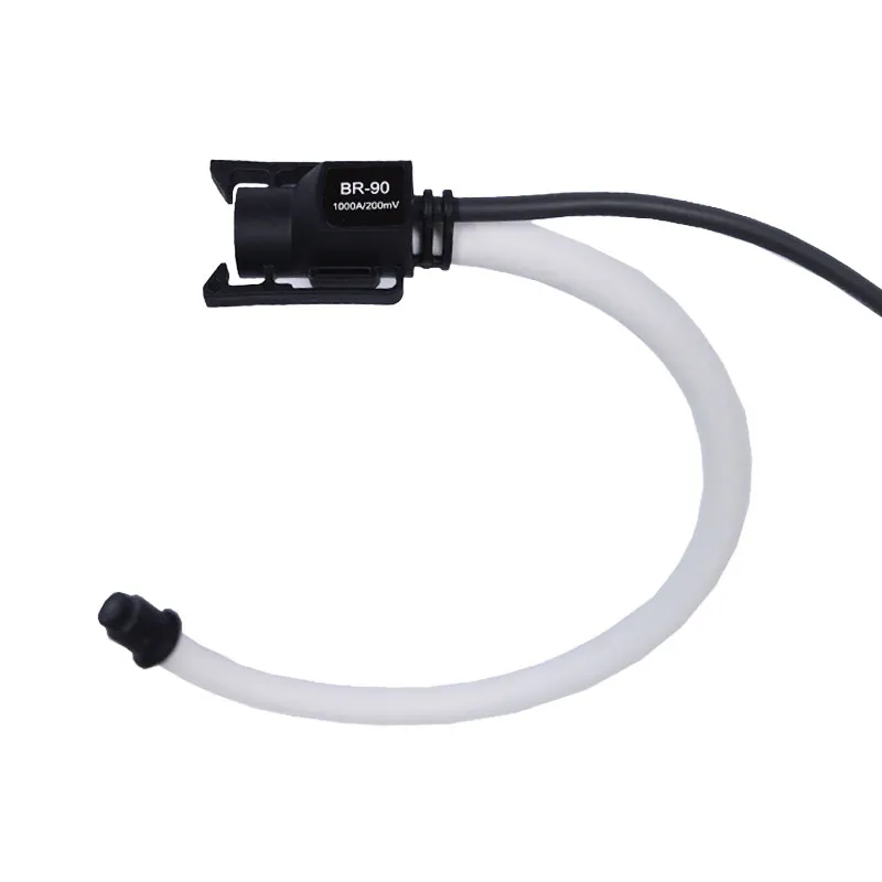
Acrel BR Series Rogowski Coil CT
● Secondary Current Output: 200mV/333mV
Series Overview
| Model Name | Primary Input [AC] | Secondary Output | Perforation Hole Size (mm) |
| BR-90 | 1000A | 200/333mV | 90 |
| BR-150 | 2000~5000A | 200mV | 150 |
| BR-200 |
4000~8000A | 200mV | 200 |
| BR-300 | 5000~10000A | 200mV | 300 |
Dimension

| Model Name | Inner Diameter | Sector Diameter | Circumference |
| BR-90 | 90mm | 12mm | 300mm |
| BR-150 | 150mm | 12mm | 500mm |
| BR-200 |
200mm | 12mm | 650mm |
| BR-300 | 300mm | 12mm | 1000mm |
Noted: The secondary signal output line is 2x0.2mm² cable with length of 2m ± 10cm.
Installation Instruction

Noted: Before installing the Rogowski CT on monitoring circuits, first you need to wire the Rogowski CT with paired energy meter.

Noted: The clamping up installation direction of CT must be according to the actual forward current direction. [Normally consider the direction from source to loads as forward current direction]
Series Overview
| Model Name | Primary Input [AC] | Secondary Output | Perforation Hole Size (mm) |
| BR-90 | 1000A | 200/333mV | 90 |
| BR-150 | 2000~5000A | 200mV | 150 |
| BR-200 |
4000~8000A | 200mV | 200 |
| BR-300 | 5000~10000A | 200mV | 300 |
General Technical Specs
● Linearity: ±0.2%
● Insulation Voltage: Coil: 3000V; Signal cable: 300V
-
BR Series Rogowski Coil Flexible Current Transformer.pdf

Related Products


CONTACT US
Contact US
Product Information
Quantity
Unit
Piece
Support order samples, customization, wholesale direct, and complete payment. If the product you look for does not have corresponding customized content, pls fill out the form below to contact us, and we will reply ASAP.