


AM5SE series Protection Relay
·Robust hardware
·Protection functions
·Rich measuring inputs
·Communication
·User-machine interface(UMI)
·Logs and Records
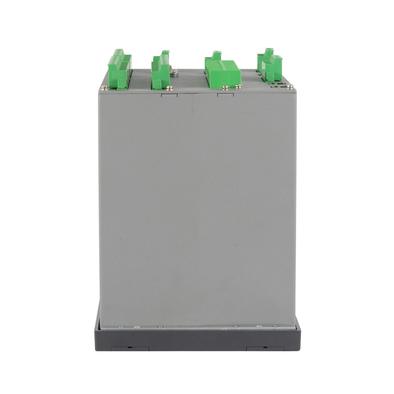
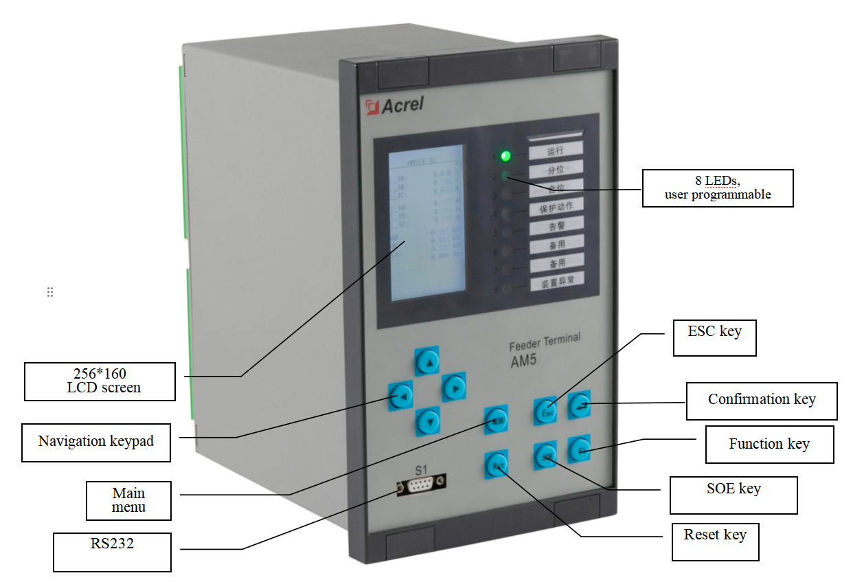
The AM5SE relay has the modular design and it can be optimized to almost all type of feeder protection applications in medium voltage distribution systems.

|
Analogue inputs |
AM5SE |
||||||||||||||
|
-F |
-T |
-M |
-C |
-MD |
-D2 |
-D3 |
-TB |
-IS |
-FE |
-FA |
-B |
-K |
-UB |
-FD |
|
|
Input current |
8 |
8 |
8 |
8 |
9 |
9 |
9 |
8 |
6 |
8 |
8 |
8 |
8 |
0 |
/ |
|
Input voltage |
6 |
4 |
4 |
4 |
4 |
4 |
4 |
4 |
8 |
6 |
6 |
6 |
6 |
8 |
/ |
|
Digital |
-F |
-T |
-M |
-C |
-MD |
-D2 |
-D3 |
-TB |
-IS |
-FE |
-FA |
-B |
-K |
-UB |
-FD |
|
Digital Input |
20 |
20 |
20 |
20 |
20 |
20 |
20 |
20 |
20 |
20 |
20 |
20 |
20 |
20 |
12 |
|
Digital Output |
10 |
10 |
10 |
10 |
10 |
10 |
10 |
10 |
10 |
10 |
10 |
10 |
10 |
10 |
64 |
|
Rear port |
-F |
-T |
-M |
-C |
-MD |
-D2 |
-D3 |
-TB |
-IS |
-FE |
-FA |
-B |
-K |
-UB |
-FD |
|
RS485 (2 ports) |
√ |
|
|||||||||||||
|
Ethernet(2 ports) |
■ |
|
|||||||||||||
|
USB(1 port) |
√ |
|
|||||||||||||
|
Protocols |
-F |
-T |
-M |
-C |
-MD |
-D2 |
-D3 |
-TB |
-IS |
-FE |
-FA |
-B |
-K |
-UB |
-FD |
|
Modbus Serial |
√ |
|
|||||||||||||
|
Modbus over Ethernet |
■ |
|
|||||||||||||
|
IEC 60870-5-103 |
√ |
|
|||||||||||||
|
TCP IEC 60870-5-103 |
■ |
|
|||||||||||||
|
IEC 60870-5-101 |
√ |
|
|||||||||||||
|
Measurement |
-F |
-T |
-M |
-C |
-MD |
-D2 |
-D3 |
-TB |
-IS |
-FE |
-FA |
-B |
-K |
-UB |
-FD |
|
4-20mA analog output |
■ |
|
|||||||||||||
|
Electric parameter |
U、I、P、Q、PF、Fr、Ep、Eq、Es |
U、I |
U、Fr |
|
|||||||||||
|
Logs and Records |
-F |
-T |
-M |
-C |
-MD |
-D2 |
-D3 |
-TB |
-IS |
-FE |
-FA |
-B |
-K |
-UB |
-FD |
|
Fault recorder |
√ |
|
|||||||||||||
|
Number of circuit breaker trip and close |
√ |
|
|||||||||||||
|
Sequence of event record |
√ |
|
|||||||||||||
|
Monitoring function |
-F |
-T |
-M |
-C |
-MD |
-D2 |
-D3 |
-TB |
-IS |
-FE |
-FA |
-B |
-K |
-UB |
-FD |
|
Trip-and-Close Circuit Supervision |
√ |
|
|||||||||||||
|
Remote control |
√ |
|
|||||||||||||
|
Others |
-F |
-T |
-M |
-C |
-MD |
-D2 |
-D3 |
-TB |
-IS |
-FE |
-FA |
-B |
-K |
-UB |
-FD |
|
GPS |
√ |
|
|||||||||||||
|
Protection Function |
-F |
-T |
-M |
-C |
-MD |
-D2 |
-D3 |
-TB |
-IS |
-FE |
-FA |
-B |
-K |
-UB |
-FD |
|
3 stages directional overcurrent (with voltage dependant)[ANSI 67] |
√ |
|
|
|
|
|
|
√ |
√ |
|
|
√ |
|
|
|
|
3 stages overcurrent (with composite voltage blocking)[ANSI 50/51] |
√ |
√ |
|
|
|
|
|
√ |
√ |
|
|
√ |
|
|
|
|
Differential protection with ratio restraining[ANSI 87] |
|
|
|
|
√ |
√ |
√ |
|
|
|
|
|
|
|
|
|
Instantaneous Differential protection[ANSI 87] |
|
|
|
|
√ |
√ |
√ |
|
|
|
|
|
|
|
|
|
Motor overcurrent(motor start,motor run,2 stages) |
|
|
√ |
|
√ |
|
|
|
|
|
|
|
|
|
|
|
Overcurrent (2 stages) [ANSI 50/51] |
|
|
|
√ |
|
|
|
|
|
|
|
|
|
|
|
|
Overcurrent IDMT [ANSI 51N] |
√ |
√ |
√ |
√ |
√ |
|
|
√ |
√ |
|
|
√ |
|
|
|
|
Bus charge |
|
|
|
|
|
|
|
|
|
|
|
√ |
|
|
|
|
Protection Function |
-F |
-T |
-M |
-C |
-MD |
-D2 |
-D3 |
-TB |
-IS |
-FE |
-FA |
-B |
-K |
-UB |
-FD |
|
Bus tie protection and standby power automatic switch |
|
|
|
|
|
|
|
|
|
|
|
√ |
|
|
|
|
2 stages Directional earth fault [ANSI 67N] |
√ |
|
|
|
|
|
|
√ |
√ |
|
|
√ |
|
|
|
|
2 stages earth fault [ANSI 50N/51N] |
|
√ |
√ |
√ |
√ |
|
|
√ |
|
|
|
|
|
|
|
|
Earth fault IDMT[ANSI 50N/51N] |
√ |
√ |
|
|
|
|
|
√ |
√ |
|
|
|
|
|
|
|
Clearance earth fault protection(2 stages) |
|
|
|
|
|
|
|
√ |
|
|
|
|
|
|
|
|
Negative sequence overcurrent (2 stages)[ANSI 46] |
|
|
√ |
|
√ |
|
|
|
|
|
|
|
|
|
|
|
Negative sequence overcurrent IDMT[ANSI 46] |
|
|
√ |
|
√ |
|
|
|
|
|
|
|
|
|
|
|
Overload [ANSI 49F] |
√ |
√ |
√ |
|
√ |
|
|
√ |
|
|
|
|
|
|
|
|
Starting air-cooled water chiller |
|
|
|
|
|
|
|
√ |
|
|
|
|
|
|
|
|
On-load tap charge lock-out |
|
|
|
|
|
|
|
√ |
|
|
|
|
|
|
|
|
Undervoltage (trip)[ANSI 27] |
|
|
√ |
|
√ |
|
|
|
√ |
√ |
√ |
|
|
|
|
|
Undervoltage (alarm)[ANSI 27] |
|
|
√ |
|
√ |
|
|
|
√ |
√ |
√ |
|
|
√ |
|
|
Capacitor undervoltage(trip) |
|
|
|
√ |
|
|
|
|
|
|
|
|
|
|
|
|
Loss of voltage (trip) |
√ |
|
|
|
|
|
|
|
√ |
|
|
|
|
|
|
|
Loss of voltage (alarm) |
√ |
|
|
|
|
|
|
|
√ |
|
|
|
|
|
|
|
Overvoltage protection[ANSI 59] |
√ |
|
√ |
√ |
√ |
|
|
|
√ |
√ |
|
|
|
√ |
|
|
Residual voltage protection(trip)[ANSI 59N] |
√ |
|
|
√ |
√ |
|
|
√ |
√ |
|
√ |
|
|
|
|
|
Residual voltage protection(alarm)[ANSI 59N] |
|
|
√ |
|
|
|
|
|
|
|
√ |
|
|
√ |
|
|
PT supervision[ANSI 60] |
√ |
√ |
√ |
√ |
√ |
|
|
√ |
√ |
√ |
√ |
√ |
|
√ |
|
|
Unbalance voltage[ANSI 60] |
|
|
√ |
√ |
√ |
|
|
|
|
|
|
|
|
|
|
|
Unbalance current[ANSI 60] |
|
|
|
√ |
√ |
|
|
|
|
|
|
|
|
|
|
|
Motor starting time-out[ANSI 48] |
|
|
√ |
|
√ |
|
|
|
|
|
|
|
|
|
|
|
CT supervision[ANSI 60] |
√ |
√ |
|
|
√ |
√ |
√ |
|
√ |
|
|
|
|
|
|
|
Three phase Auto-reclose[ANSI 79] |
√ |
|
|
|
|
|
|
|
|
|
|
|
|
|
|
|
Thermal overload protection[ANSI 49M] |
|
|
√ |
|
√ |
|
|
|
|
|
|
|
|
|
|
|
Locked rotor[ANSI 51LR] |
|
|
√ |
|
√ |
|
|
|
|
|
|
|
|
|
|
|
FC block[ANSI 86] |
√ |
√ |
√ |
|
√ |
|
|
√ |
√ |
|
|
|
|
|
|
|
Post-accelerated overcurrent |
√ |
|
|
|
|
|
|
|
|
|
|
√ |
|
|
|
|
Under frequency[ANSI 81U] |
√ |
|
|
|
|
|
|
|
√ |
√ |
√ |
|
|
|
|
|
Over frequency[ANSI 81O] |
√ |
|
|
|
|
|
|
|
√ |
√ |
√ |
|
|
|
|
|
Incorrect phase sequence |
|
|
√ |
|
√ |
|
|
|
|
|
|
|
|
|
|
|
Voltage Phase loss protection |
|
|
√ |
|
√ |
|
|
|
|
|
|
|
|
|
|
|
Directional power protection[ANSI 32] |
√ |
|
|
|
|
|
|
|
√ |
|
|
|
|
|
|
|
Power recovery protection |
|
|
|
|
|
|
|
|
√ |
|
|
|
|
|
|
|
Under power protection |
|
|
|
|
|
|
|
|
√ |
|
|
|
|
|
|
|
Non-electricity |
√ |
√ |
√ |
√ |
√ |
|
|
√ |
√ |
|
|
|
|
|
√ |
|
PT supervision and parallel connection |
|
|
|
|
|
|
|
|
|
|
|
|
|
√ |
|
|
Synchro-check[ANSI 25] |
√ |
|
|
|
|
|
|
|
√ |
|
|
√ |
|
|
|
|
Rate of change of frequency[ANSI 81R] |
|
|
|
|
|
|
|
|
√ |
√ |
|
|
|
|
|
|
Trip-and-Close Circuit Supervision(alarm) |
√ |
√ |
√ |
√ |
√ |
|
|
√ |
√ |
√ |
√ |
√ |
|
|
|
|
Protection Function |
-F |
-T |
-M |
-C |
-MD |
-D2 |
-D3 |
-TB |
-IS |
-FE |
-FA |
-B |
-K |
-UB |
-FD |
|
Auto-close with voltage recovery |
|
|
|
|
|
|
|
|
√ |
|
|
|
|
|
|
|
PT harmonic elimination |
|
|
|
|
|
|
|
|
|
|
|
|
|
√ |
|
|
Overhaul-lockout[ANSI 86] |
√ |
||||||||||||||
Rated Characteristics
|
Characteristics Version |
AM5SE-F,AM5SE-T,AM5SE-M,AM5SE-C, AM5SE-B,AM5SE-D2,AM5SE-D3, AM5SE-TB,AM5SE-MD |
AM5SE-UB, AM5SE-IS, AM5SE-FE, AM5SE-FA,AM5SE-K |
|
Power Supply |
||
|
Rated voltage |
AC/DC 110V or AC/DC 220V |
|
|
Range |
Rated voltage × (1±20%) |
|
|
Burden |
≤15 VA |
|
|
PT Inputs |
||
|
Rated value |
AC 100V or V |
AC 380V or 220V |
|
PT rated secondary range |
0.1V~120V |
0.1V ~ 456V |
|
Accuracy |
0.5S |
|
|
Burden |
≤0.5VA (each phase) |
|
|
Voltage withstand |
Continuous: 1.2 Un 10s: 2 Un |
|
|
Phase CT Inputs (Protection Current) |
||
|
CT rated secondary range |
AC 5A or 1A |
|
|
Dynamic |
20 × CT rated current |
|
|
Accuracy |
0.5S |
|
|
Burden |
≤0.5VA (each phase) |
|
|
Thermal withstand |
Continuous: 2 In 1s: 40 In |
|
|
Phase CT Inputs (Measurement Current) |
||
|
CT rated secondary range |
AC 5A or 1A |
|
|
Dynamic |
1.5 × CT rated current |
|
|
Accuracy |
0.5S |
|
|
Burden |
≤0.5VA (each phase) |
|
|
Thermal withstand |
Continuous: 1.5 In 1s: 4 In |
|
|
Frequency |
||
|
50Hz or 60Hz |
||
|
40 ~ 70Hz |
||
|
±0.1Hz |
||
|
Digital Inputs |
||
|
AC/DC 110V or AC/DC 220V |
||
|
70% of nominal voltage |
||
|
55% of nominal voltage |
||
|
≤ 1W (each phase) (DC220V) |
||
|
Digital Outputs |
||
|
≥ 10000 operations |
||
|
≥ 1000W, L / R = 40ms |
||
|
≥ 5A |
||
|
≥ 30A for 200ms |
||
|
≥ 30W, L/R = 40ms |
||
Protection characteristics
|
Characteristics |
Accuracy |
Resolution |
Disengaging ratio |
|
Voltage |
±3% |
0.001V |
0.95 and 1.05 |
|
Current |
±3% |
0.001A |
0.95 and 1.05 |
|
Frequency |
±0.02Hz |
0.001Hz |
|
|
Operation delay|t>(DT) |
40ms or ±2% setting value |
0.001s |
- |
|
Operation delay|t>(IDMT) |
40ms or ±5% setting value |
0.001s |
- |
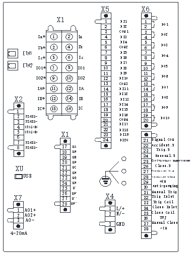
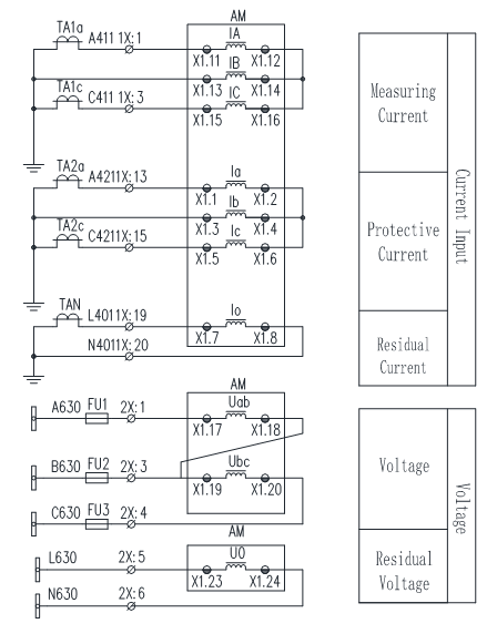
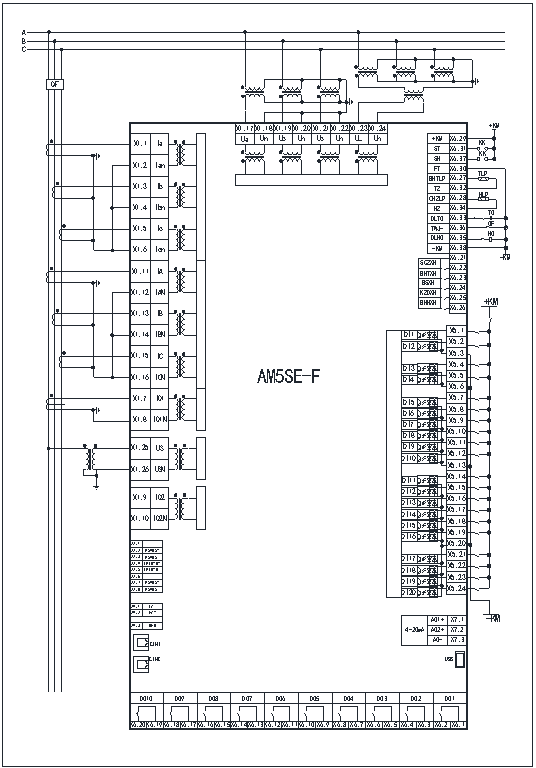
X1 1-16 Current
X1 17-28 Voltage
X2 1-8 RS-485 and IRIG-B
X4 1-2 Power supply
X4 3 Power ground
X5 1-24 Digital inputs
X6 1-20 Digital outputs
X6 21-38 Anti-pumping and trip and close supervision
X7 1-3 Analog output
ETH 1-2 Ethernet
XU USB
2PT &2CT Wiring
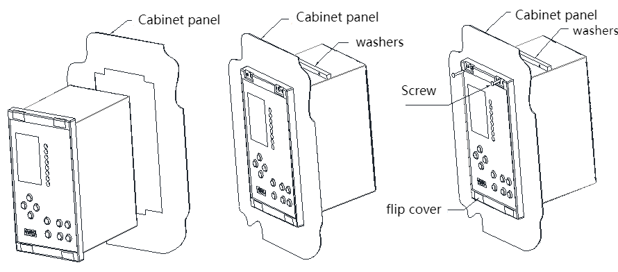
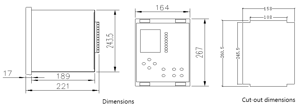
1.Prepare the cut-out in the panel for the flush installation according to the above dimensions.
2.Fasten the AM5SE protection relay in its position with for four M3×12mm screws with washers.
3.Cover four small flip covers on the four screws again.
-
AM5SE series Protection Relay-V1.5-202411221533.pdf

Related Products


CONTACT US
Contact US
Product Information
Quantity
Unit
Piece
Support order samples, customization, wholesale direct, and complete payment. If the product you look for does not have corresponding customized content, pls fill out the form below to contact us, and we will reply ASAP.